|
|---|

| Home |
|
|
|
FAQ | Forum | Links |
| Translate: |
|
Updated: Jan 9, 2021
If you would like custom software for your application, such as: new parameters, scales and graphs, please contact Bob directly: Bob@w5big.com |
|
=== For service on AIM or VNA hardware, contact:=== [email protected] |
|
April 4, 2018
If your AC power distribution system uses only two wires, here are some tip on things to watch out for. |
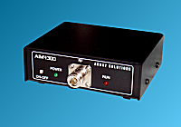
*** The AIM4300 from Array Solutions has been discontinued.
*** You can consider this alternative line of VNA's:
DG8SAQ VNAW3 Analyzer
|
Jan 9, 2021:
The latest version of the VNA2180 program is version VNA_546B The latest version of the VNAuhf program is version VNAuhf_636 |
Click for more information on the AIM4300 .
The AIM4300 is the replacement for the AIM4170D. The AIM4300 and AIMuhf run the latest AIM software and |
|
Jan 5, 2013
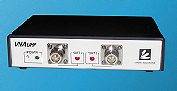
Features similar to the VNA2180 with coverage up to 1 GHz. Click for more information on the VNAuhf .
|
Dec 8, 2012
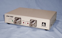 VNA2180 Vector Network Analyzer *** The VNA2180 from Array Solutions has been discontinued.
|
|
Introduced Jan 9, 2011
Feb, 2019: Same features as the AIM4300 with coverage up to 1 GHz. Click for more information on the AIMuhf . *** The AIMuhf from Array Solutions has been discontinued.
|
Nov 30, 2016:
New features include:
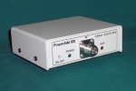
The new PowerAIM-150 was introduced at the National Association of Broadcasters (NAB) Show in Las Vegas in April, 2017. The predecessor of the PowerAIM-150, the PowerAIM-120, was very well received at the NAB in 2008, winning two awards at that show: |
|
Jan 8, 2014
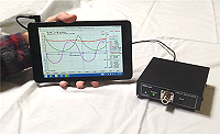
New tablet computers can run the AIM and VNA programs to provide a very compact test unit for field operation while retaining precision for lab use. Here is a document with more details on setting up the tablet. |
Application Notes by Larry, W0QE: Sept 18, 2011: Aug 24, 2011: |
|
June 11, 2011: |
Apr 15, 2010: |
|
Dec 12, '09: |
June 12, '08: |
|
July 16, '08: |
Mar 5, '08:
|
| Dec 26, '07: Information for using the AIM4170 with a Mac has been provided by KH6ZZ. |
July 10, '07:
See the QST product review of the AIM4170 in the August '07 issue. ARRL Bottom Line: |
| This article in Nov, '06 QST describes an earlier version of the AIM which covered the HF band up to 32 MHz. The principles of operation are the same as the AIM4170. It is presented here with permission of the ARRL. |
Checkout the AIM4170 reviews at eHam.net. |
| This article in the Nov/Dec '06 issue of NCJ describes an earlier version of the AIM which covered the VHF band up to 160 MHz. The principles of operation are the same as the AIM4170. It is presented here with permission of the ARRL. |
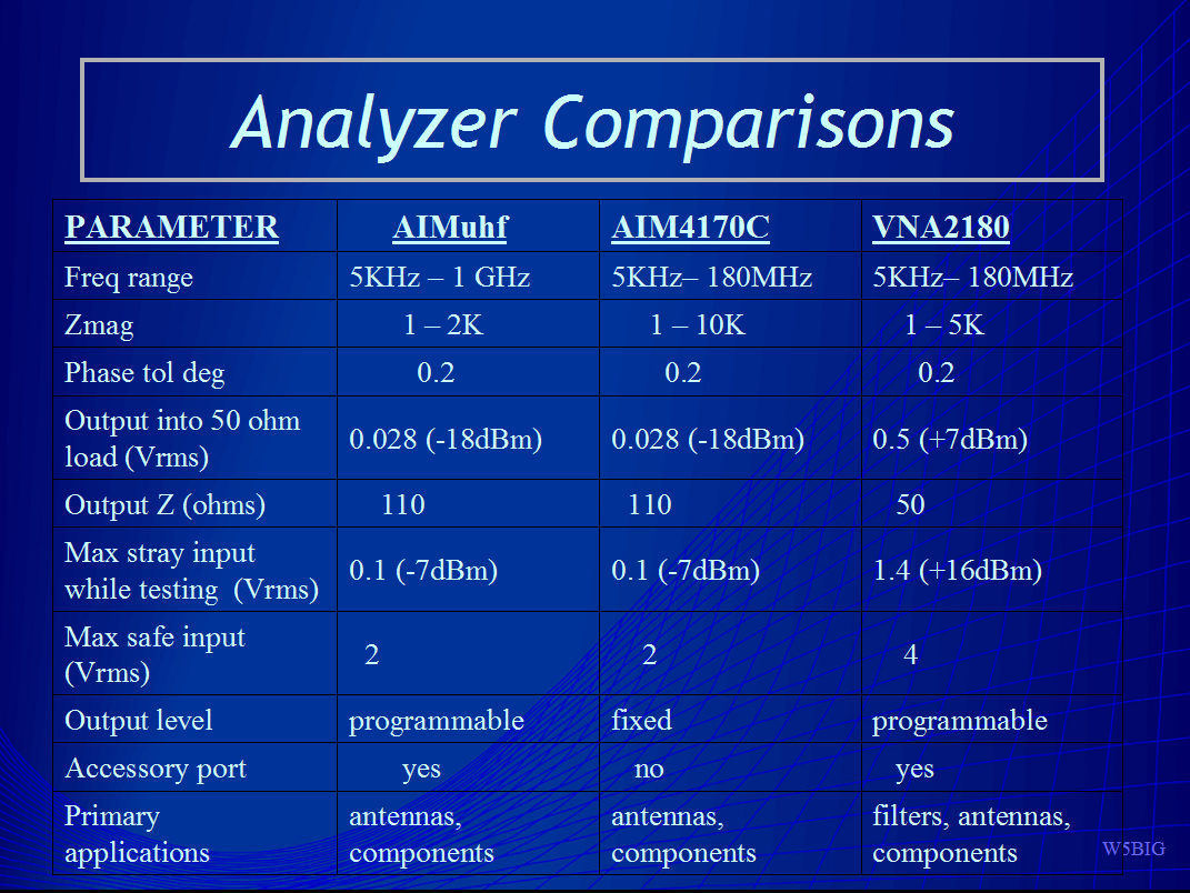
The AIM4160/4170 compared with several other antenna analyzers. |
| A comparison of several network and impedance analyzers, including the AIM4170, by Rudy Severns N6LF. |
5/7/07: The AIM4170 tolerance to external RF signals is illustrated here. |
|
7/27/07: If you would like to make a club presentation, you are welcome to use the AIM4170 Power Point slide show. |
Here is a very nice program for graphically processing AIM scan data for off-line analysis and presentations: Zplots by AC6LA |

Updated: July 23, 2018
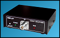
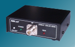
antenna analyzer
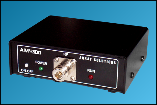 AIM4300 (with optional N-connector)
(The earlier AIM4170 model has been replaced by the AIM4300 model. The basic operating principles are similar. - July, 2018). This new antenna analyzer measures the complex impedance (magnitude and phase) at each frequency of interest in the range of 0.05 to 300 MHz. A PC is used to calculate several parameters, including SWR, and plot the results. The test frequency is generated digitally and bandpass filters are used to reject stray signals (like broadcast stations) that are more than a few KHz from the operating frequency. A 12 bit analog to digital converter digitizes the raw data. This avoids non-linearities associated with diode detectors, and results in very good dynamic range and linearity for accurate magnitude and phase measurements. Impedance measurements can range up to 10K ohms. The true phase angle is measured, so inductive or capacitive reactance can be determined without ambiguity. The RF generator can also be used as a signal source for testing receivers. The frequency is very stable and it can be calibrated to WWV. The digitized data is sent to the PC via an RS232 or USB port. Power for the analyzer can be obtained from a small DC power supply or a battery. With a laptop computer, the unit is quite portable and it can even be mounted up on a tower at the antenna feed point if desired, with power being supplied through the RS232 cable. The impedance at the antenna itself can be read with the AIM4300 located in the shack at the receiving/transmitting end of the coax. The cable can be any length. The cable's impedance and loss characteristics are determined by a simple calibration procedure and the antenna's impedance is plotted directly during the scan. There are no internal adjustments. The complete calibration is done using software and calibration standards included with the analyzer. The frequency range is continuous from 5 KHz to 300 MHz. Some of the parameters that are calculated by the PC include:
The scan data can be saved to disk or printed to compare before and after results. It can also be imported in spreadsheet programs for further analysis. The program has been tested with Windows 98, 2000, ME, XP, Vista, Win 7, Win 8.1 and Win 10. It does not require an installation procedure. (It will run directly from a CD, a floppy disk or a flash drive.) The display can be scaled for use on any size computer monitor. The unit of length used for input/output data can be selected as feet or meters. (The following pictures show screen shots taken with an AIM4170 which is equivalent to the AIM4300 over its frequency range) 15 meter dipole antenna. Scan = 20.5 to 22.5 MHz.
Open coaxial cable approximately 28 feet long. Scan = 4 to 14 MHz Same cable as above. Scan = 10.5 MHz to 12.5 MHz 
Scan of unterminated coax and Smith chart. Scan = 5 to 25 MHz 
|